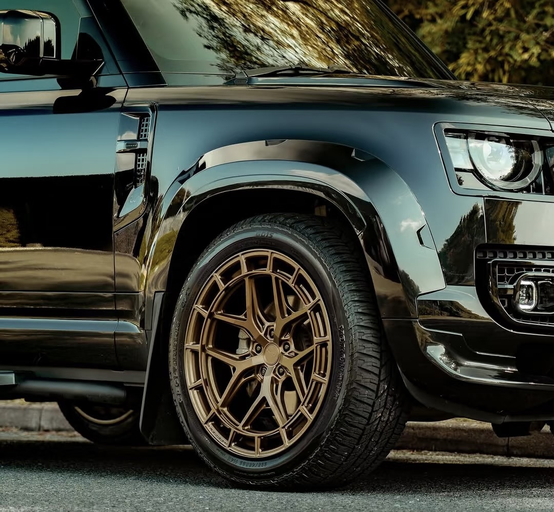
Automotive Alloy Wheels: Engineering, Performance, and Complete Selection Overview
Automotive Alloy Wheels: Engineering, Performance, and Complete Selection Overview
Every vehicle enthusiast, daily commuter, and fleet operator eventually faces a pivotal upgrade decision: replacing factory-stamped steel wheels with aftermarket automotive alloy wheels.
Beyond visual styling and curb appeal, modern wheel production represents an intersection of structural metallurgy, fluid dynamics, heat dissipation engineering, and multi-axis mechanical geometry. Upgrading your wheel setup fundamentally transforms how your vehicle handles dynamic loads, responds to throttle inputs, dissipates severe braking heat, and maintains tire contact patches on uneven road surfaces.
Understanding the structural science, raw material formulations, manufacturing trade-offs, and exact measurement parameters ensures you invest in a setup that maximizes performance, enhances durability, and delivers uncompromised safety.
1.What Are Automotive Alloy Wheels Made Of?
Automotive alloy wheels are metallic structural rims engineered from a non-ferrous composite blend consisting primarily of aluminum combined with precise proportions of secondary strengthening elements like silicon, magnesium, copper, nickel, or titanium.
Unlike conventional steel wheels, which are stamped from heavy iron-carbon sheet metal and welded together, modern alloy formulations leverage non-ferrous physical chemistry to optimize strength-to-weight ratios.
Comprehensive Metallurgical Breakdown
The performance characteristics of an automotive alloy wheel are governed by its exact chemical composition. Commercial structural alloys (such as A356.2 for casting or 6061-T6 for forging) rely on specific elemental balances:
-
Aluminum (Base Metal – ~85% to 92%): Serves as the lightweight foundational matrix. It possesses a density approximately one-third that of structural steel, providing low mass alongside natural passivation against environmental oxidation.
-
Silicon (Fluidity & Hardness Agent – ~7% to 11%): Introduced into liquid casting mixtures to lower melting viscosity and increase mold filling fluidity. Once solidified, silicon particles form a micro-crystalline structure that increases surface scratch resistance and mechanical yield strength.
-
Magnesium (Tensile & Fatigue Resistance – ~0.3% to 1.5%): Significantly boosts tensile strength and strain hardening properties when thermal heat treatment is applied. This permits engineers to design thinner spoke geometries without compromising structural fatigue limits.
-
Copper & Manganese (Structural Durability – ~0.2% to 0.5%): Added in controlled quantities to improve yield limit endurance under high-temperature cycling caused by aggressive braking loads.
-
Titanium (Grain Refiner – ~0.1% to 0.2%): Acts as a nucleation agent during solidification, creating an ultra-fine crystal grain structure that inhibits internal micro-fissure propagation under heavy mechanical stress.
By adjusting these exact metallurgical ratios and controlling thermal tempering cycles (such as T6 heat treatment involving solution heat exposure, liquid quenching, and artificial aging), manufacturers engineer specific wheel lines tailored for lightweight racing setups, off-road applications, or heavy payload demands.
2.Automotive Alloy Wheels vs. Steel Wheels: Key Differences
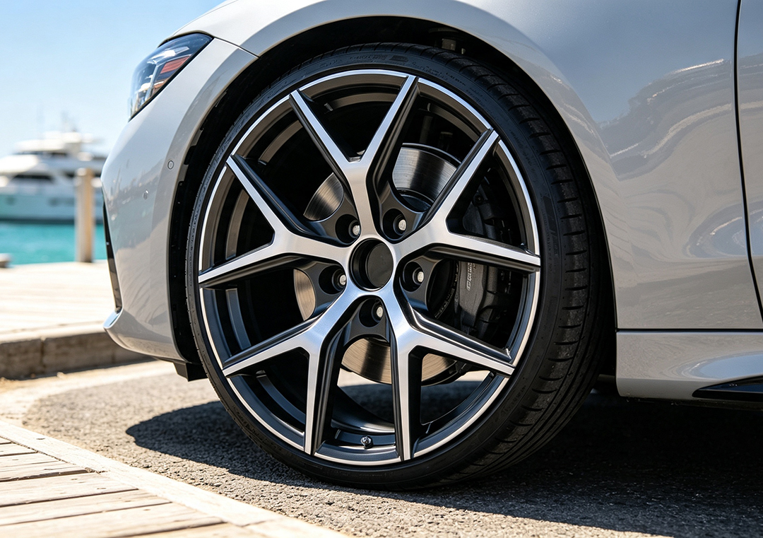
When evaluating wheel options, comparing alloy choices against traditional stamped steel configurations involves four fundamental engineering factors: mass distribution, structural rigidity, thermal conductance, and long-term economic cost.
| Evaluation Metric | Automotive Alloy Wheels | Heavy-Duty Stamped Steel Wheels |
|---|---|---|
| Primary Material | Aluminum-Silicon-Magnesium Composite | Stamped Carbon Sheet Steel / Iron |
| Unsprung Mass | Lightweight (14 lbs - 24 lbs average) | Heavy (26 lbs - 42+ lbs average) |
| Manufacturing Method | Mold Casting, Flow-Forming, or CNC Forging | Hydraulic Press Stamping & Circumferential Welding |
| Thermal Dissipation | High thermal conductivity; rapid brake cooling | Low thermal conductivity; traps brake heat |
| Impact Tolerance | Rigid; absorbs stress, cracks under extreme overload | Ductile; deforms/bends easily under heavy impacts |
| Geometric Precision | Machined tolerances within thousandths of an inch | Stamped tolerance; higher radial runout variation |
| Design Versatility | Complex multi-spoke, deep concave, custom finishes | Uniform utility shapes; requires plastic hubcaps |
| Corrosion Response | Highly resistant to rust; clear coat protection | Prone to rapid surface oxidation if paint chips |
| Cost Range | Moderate to Premium | Low / Budget Entry-Level |
Unsprung Mass and Vehicle Dynamic Physics
The primary functional benefit of automotive alloy wheels centers on lowering unsprung mass. Unsprung mass refers to all mechanical components situated below the vehicle’s suspension springs, including the wheels, tires, brake rotors, calipers, and hub bearings.
Reducing unsprung mass transforms vehicle dynamics in three distinct physical areas:
1. Suspension Response and Contact Patch Retention
When a tire encounters a bump or surface imperfection, the energy pushes the wheel assembly upward. A lighter alloy wheel generates less kinetic momentum during this vertical displacement. Consequently, the suspension damper and spring return the tire to the pavement faster, maintaining a consistent tire contact patch and maximizing cornering traction.
2. Rotational Inertia and Acceleration Metrics
Rotational inertia dictates how much engine torque is required to spin an object up to speed. Because alloy wheels concentrate less mass along the outer rim barrel compared to steel wheels, the engine encounters less rotational resistance. This delivers faster throttle response, immediate low-speed pickup, and improved fuel efficiency during urban stop-and-go driving.
3. Kinetic Braking and Thermal Dissipation
Bringing a moving vehicle to a stop requires converting kinetic energy into thermal energy via brake pad friction. Lighter wheels decrease total kinetic energy. Furthermore, aluminum alloys feature thermal conductivity roughly three times higher than steel. Open-spoke alloy designs draw cool air across the rotor face, pulling heat away from brake fluid and reducing thermal brake fade during aggressive mountain driving or track use.
3.Manufacturing Processes: Cast, Flow-Formed, and Forged Alloys
Not all alloy wheels are manufactured using the same techniques. The chosen manufacturing method directly determines internal structural density, tensile strength, overall weight, fatigue threshold, and final price point.
1. Cast Alloy Wheels
Casting is the most widespread manufacturing technique for OEM factory wheels and aftermarket replacements. The process involves heating aluminum alloy into a liquid state (~1,300°F / 700°C) and introducing it into a precision-machined steel mold.
-
Gravity Casting: Liquid aluminum is poured into the mold using only atmospheric gravity. While cost-effective, gravity casting allows tiny microscopic gas pockets to form during cooling, resulting in lower structural density. To compensate, manufacturers must use thicker spoke designs, making the final product slightly heavier.
-
Low-Pressure Casting: Liquid metal is drawn upward into the mold from a sealed crucible using controlled pneumatic pressure. This constant upward pressure forces air bubbles out and packs the molten aluminum tightly together. Low-pressure casting yields higher structural density, superior impact tolerance, and lighter weight than gravity casting.
Ideal Applications: Everyday passenger commuters, winter wheel setups, and cost-conscious styling upgrades.
2. Flow-Formed Alloy Wheels
Flow-forming (frequently referred to as rotary forging, rim-rolling, or flow-forging) bridges the performance gap between casting and high-end forging.
The process begins with a specialized low-pressure cast preform wheel. The wheel’s center hub and spokes are already cast, but the barrel portion is produced narrow and thick.
[Cast Preform Wheel]
       │
       ▼ (Mounted onto Heated Spinning Mandrel)
[High-Speed Rotation + Hydraulic Pressure Rollers]
       │
       ▼ (Aluminum Barrel Stretched & Compressed)
[Flow-Formed Wheel with Refined Grain Alignment]
-
The preform is mounted on a heated mandrel and spun at high speeds.
-
Hydraulic pressure rollers press firmly against the spinning aluminum barrel.
-
The intense heat and mechanical pressure stretch, compress, and shape the metal barrel down to its final width.
This combination of radial pressure and axial force reorganizes the aluminum’s internal molecular grain matrix, aligning the molecules along the flow path. The final product exhibits thin, ultra-strong barrel walls with mechanical properties comparable to forged wheels at a lower cost point.
Ideal Applications: Sports sedans, track day enthusiasts, autocross vehicles, and performance upgrades.
3. Forged Alloy Wheels
Forged wheels represent the highest tier of modern wheel engineering. Forging eliminates liquid metal casting entirely.
Production begins with a solid, cylindrical billet of aerospace-grade 6061-T6 aluminum alloy. This solid block is heated and placed inside an industrial hydraulic press that exerts 8,000 to 10,000 tons of pressure to compress the metal into a blank shape.
-
Molecular Compression: The extreme hydraulic pressure eliminates internal microscopic voids and forces the aluminum grain structure into a dense, continuous flow line.
-
Precision CNC Milling: Once the forged blank cools, computer-controlled multi-axis CNC milling machines carve out complex spoke patterns, hub pockets, and weight-reduction channels directly from the solid block.
-
Pros: Exceptional tensile strength, minimum structural weight, superior fatigue endurance, and fully customizable engineering options.
-
Cons: Premium cost due to specialized industrial equipment, high machinery wear, and material waste during milling.
Ideal Applications: Dedicated race cars, high-performance supercars, heavy-payload off-road trucks, and high-end luxury vehicle builds.
4.Vehicle Fitment Specifications: Getting the Math Right
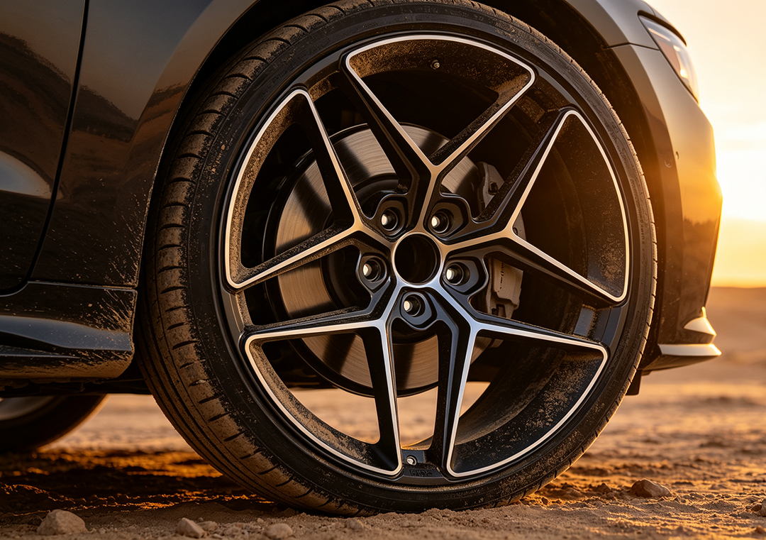
Installing new automotive alloy wheels requires exact geometric alignment. Mismatched wheel specifications can lead to severe tire rubbing against inner wheel wells, brake caliper binding, steering wheel vibration at highway speeds, or accelerated bearing failure.
Confirm four essential measurement parameters before making a selection:
1. Bolt Pattern / Pitch Circle Diameter (PCD)
The bolt pattern specifies the number of lug holes on the wheel face and the diameter of the circle they form.
-
Measurement Format: 5×114.3 (5 lug holes positioned across a 114.3 millimeter circle diameter) or 5×120.
-
Crucial Rule: The bolt pattern must match the hub studs on your vehicle axle precisely. Never attempt to force mismatched bolt patterns using slotted holes or modified lugs.
2. Wheel Diameter and Wheel Width
Wheel dimensions are measured in inches along two internal boundary points (e.g., 19×9.5).
-
Wheel Diameter (19″): The distance across the circular face from tire bead seat to tire bead seat.
-
Wheel Width (9.5″): The internal distance measured between the inner and outer rim bead flanges where the tire seats.
-
Sizing Constraint: When increasing wheel diameter (known as “plus-sizing”), you must lower the tire’s sidewall aspect ratio accordingly. The total overall outer diameter of the tire assembly should remain within 1% to 2% of factory specifications to maintain accurate speedometer readings, ABS sensor inputs, and gear calibration.
3. Wheel Offset (ET Metric)
Offset (stamped as an ET value from the German term Einpresstiefe) is the measured distance in millimeters between the wheel’s true width centerline and the flat hub mounting surface on the back of the wheel.
-
Positive Offset (+ET): The hub mounting pad sits closer to the outer front face of the wheel. This pulls the wheel inward toward the suspension. Common on modern front-wheel-drive passenger cars and crossovers.
-
Zero Offset (ET0): The hub mounting pad sits flush with the exact technical centerline of the rim width.
-
Negative Offset (-ET): The hub mounting pad sits recessed deep inside the back barrel, pushing the outer face outward away from the vehicle body. Common on lifted trucks, wide-body race builds, and classic rear-wheel-drive muscle cars.
       [ Inner Suspension ]        [ Centerline ]        [ Outer Fender ]
                │                        │                        │
  Positive Offset (+ET) ◄────── Hub Mounting Surface ──────► Negative Offset (-ET)
An incorrect offset causes inner tire scrubbing against shock absorbers or outer fender lip contact during suspension compression.
4. Center Bore Size and Hub-Centric Mechanics
The center bore is the circular hole machined into the exact back center of the wheel hub. This opening seats over the lip extending from the vehicle’s axle hub.
-
Hub-Centric Alignment: The wheel’s center bore matches the vehicle axle hub snout down to fractions of a millimeter. The vehicle’s static weight rests directly on the solid central hub hub-snout, while the lug nuts simply hold the wheel tight against the mounting face.
-
Lug-Centric Alignment: The wheel center bore is larger than the vehicle’s hub snout. If installed without adapters, the lug studs carry the vehicle’s dynamic weight, leading to wheel wobble, vibration at speed, and eventual stud shear under severe stress.
-
Correction: When installing aftermarket wheels with larger center bores, you must install hub-centric rings (polycarbonate or aluminum sizing inserts) to bridge the physical space.
5.Surface Finishing Options and Protective Coatings
The outer finish on an alloy wheel serves two primary purposes: defining the visual styling and protecting the raw aluminum structure from ambient moisture, road de-icing salts, corrosive brake dust, and UV degradation.
-
Powder Coating: Thermo-reactive plastic dry powder sprayed electrostatically onto a bare alloy surface, then baked in an industrial oven at over 400°F (204°C). This creates a durable outer skin that resists stone chips, road debris, and winter salt corrosion.
-
Multi-Stage Wet Painting: Features an electrostatic primer base, a custom color coat layer (metallic, satin, gloss, or matte hues), and a UV-resistant clear topcoat. Wet painting offers high color versatility and sharp depth.
-
Machine-Faced / Diamond Cut Finish: The wheel is painted and cured, then mounted inside a vertical CNC lathe. A diamond-tipped cutting tool shaves a microscopic layer of aluminum off the outer face, exposing bright bare metal that creates a high-contrast finish against painted spoke windows.
-
Anodizing: An electrochemical bath treatment that converts the outer aluminum surface into a hard, integrated metal oxide finish. Anodizing provides high surface hardness and unique color tints without adding thick coating weight, making it popular for racing applications.
6.Maintenance and Care for Long-Term Durability
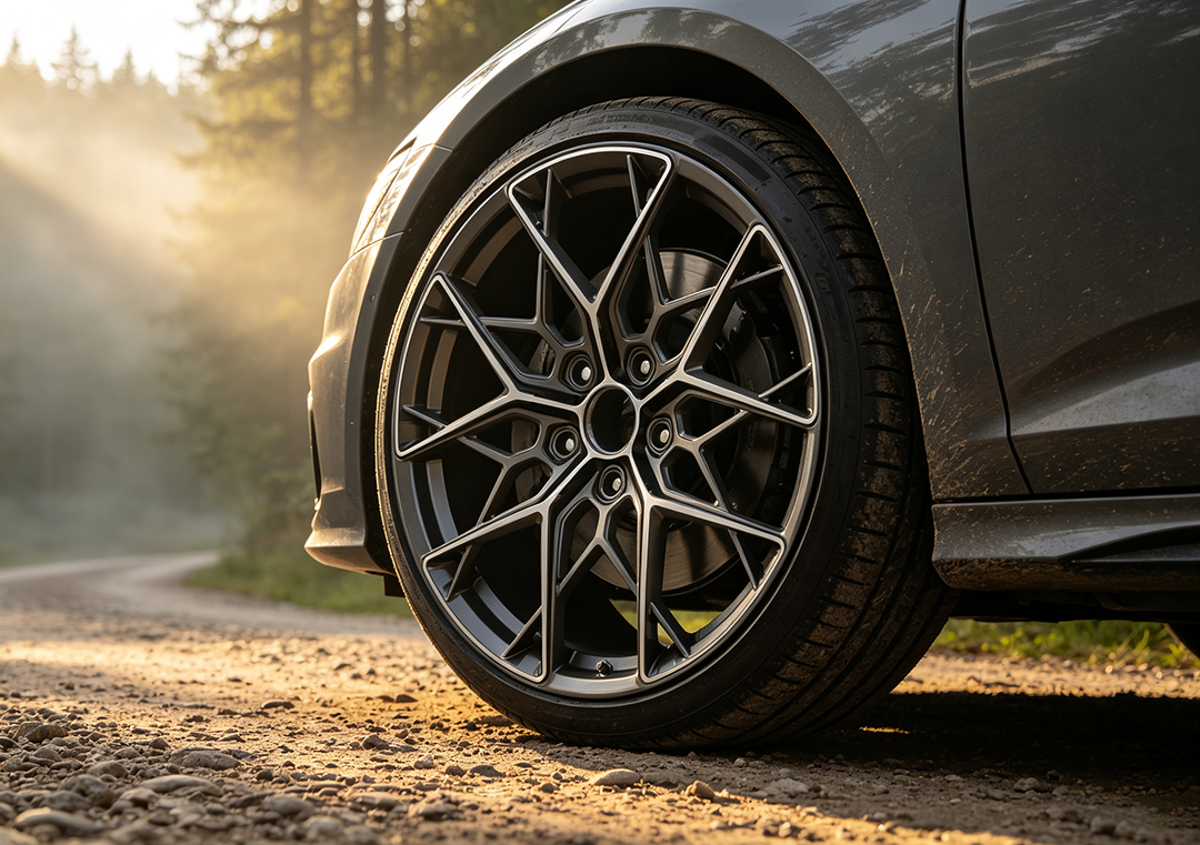
Maintaining automotive alloy wheels demands specific care practices to preserve surface clarity and prevent structural damage or corrosion pitting over time.
1. Cleaning Protocols and Chemical Selection
Never clean alloy wheels with harsh industrial acid washes or heavy alkaline degreasers. These aggressive chemicals strip protective clear coats, dull anodized finishes, and etch bare aluminum accents. Use pH-balanced car shampoos or dedicated non-acid wheel cleaners alongside soft microfiber brushes.
2. Thermal Management During Washing
Always allow wheels and brake components to cool down fully to ambient temperatures before spraying water or cleaning solutions onto the surface. Applying cold liquids to hot brake rotors and alloy surfaces can cause thermal shock, which can warp brake rotors or crack clear coat layers.
3. Hydrophobic Protection and Ceramic Sealants
Brake dust consists of microscopic hot metallic shavings created when brake pads press against rotors. If left on wheel barrels, these iron particles burn into clear coats and cause permanent pitting oxidation. Applying a synthetic wheel wax or ceramic coating creates a smooth barrier, keeping brake dust from bonding and making routine washing easier.
4. Precision Torque Speeds and Sequence
Always torque wheel lug nuts using a calibrated mechanical torque wrench set to factory specifications. Never rely entirely on pneumatic impact wrenches. Over-torquing or tightening lugs in an incorrect sequence distorts the alloy wheel lug seats, creates radial runout, and can warp brake rotor mounting surfaces.
       Lug Tightening Sequence (5-Lug Star Pattern)

                           ( 1 )

               ( 4 )                   ( 3 )

                   ( 2 )           ( 5 )
Frequently Asked Questions(FAQ)
1.What are automotive alloy wheels made of?
Automotive alloy wheels are manufactured using an aluminum composite alloyed with secondary elements like silicon, magnesium, copper, and manganese. This metal combination yields high structural strength, lightweight dynamic properties, and versatile aesthetic styling options compared to standard iron steel rims.
2.What is the main difference between alloy wheels and steel wheels?
The primary difference lies in overall mass, heat management, and dynamic performance. Alloy wheels are significantly lighter, which enhances fuel efficiency, steering handling, and acceleration response while cooling brake components fast. Steel wheels are heavier, cheaper, and flex under heavy impacts, making them preferred for heavy-duty winter setups or budget utility applications.
3.What are the primary types of automotive alloy wheels by manufacturing process?
They fall into three main manufacturing classifications:
-
Cast Alloy Wheels: Molten liquid alloy poured into molds; budget-friendly and versatile in design.
-
Forged Alloy Wheels: Machined from solid aluminum billets under extreme pressure; lighter, stronger, and built for premium applications.
-
Flow-Formed Alloy Wheels: A hybrid method combining low-pressure casting with high-speed rotary stretching for optimal strength-to-weight balance.
4.How do I choose the correct size and fitment for automotive alloy wheels?
To guarantee precise vehicle fitment without clearance issues, confirm four critical specifications:
-
Bolt Pattern (PCD): Must match your vehicle hub’s bolt circle geometry.
-
Diameter and Width: Must fit within fender wells without rubbing suspension components.
-
Offset (ET): Controls how far inward or outward the rim face sits relative to the body structure.
-
Center Bore: Ensures the wheel seats hub-centrically onto the vehicle axle hub.
5.Can cracked or bent alloy wheels be safely repaired?
Cosmetic scrapes and slight radial bends can usually be straightened and refinished by specialized rim restoration facilities. However, severe structural warps, deep cracks along spoke bases, or fractures near the center hub compromise structural integrity and require immediate replacement rather than welding or heating repairs.
Ready to Upgrade Your Vehicle’s Stance and Driving Performance?
Upgrading to a set of precision-engineered automotive alloy wheels transforms your driving experience through reduced unsprung mass, improved heat dissipation, and refined exterior stance.
At ATK Wheels, we offer precision-engineered alloy wheels designed to meet strict structural load ratings and exact fitment specifications across popular automotive platforms.
Explore our wheel collections, check your vehicle fitment parameters, and connect with our technical specialists today to select the optimal wheel setup for your vehicle.