The Science of Modern Wheel Design: Engineering, Fitment, and Driving Dynamics
The Science of Modern Wheel Design: Engineering, Fitment, and Driving Dynamics
When evaluating a vehicle, observers instantly notice its paint finish, body lines, and stance. However, few individual components influence both visual appeal and mechanical behavior as profoundly as automotive wheel design.
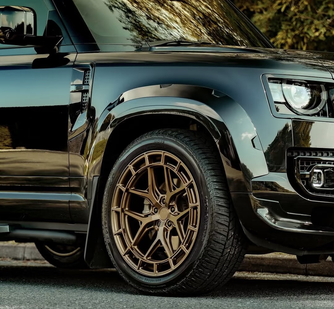
At its core, modern automotive wheel design goes far beyond aesthetics. It sits directly at the intersection of structural physics, aerodynamic efficiency, thermodynamics, and precision geometry. Whether applied to an electric sedan, a track-focused sports car, or a heavy-duty off-road truck, every line, spoke angle, and metal alloy chosen during engineering dictates how a vehicle stops, turns, accelerates, and handles structural stress.
1.What Factors Must Be Considered in Automotive Wheel Design?
Engineers must navigate a complex landscape of trade-offs when developing a custom rim. A visually striking wheel is ineffective if it fails under cornering load or adds excess weight that degrades suspension performance.
       +-------------------------------------------------------------+
       |             CORE AUTOMOTIVE WHEEL DESIGN TRIAD              |
       +------------------------------+------------------------------+
                                      |
         +----------------------------+----------------------------+
         |                            |                            |
         v                            v                            v
+------------------+        +-------------------+        +-------------------+
| STRUCTURAL       |        | PERFORMANCE       |        | FITMENT           |
| INTEGRITY        |        | ENGINEERING       |        | SPECIFICATIONS    |
| - Load Ratings   |        | - Mass Reduction  |        | - Bolt Pattern    |
| - Impact Test    |        | - Aerodynamics    |        | - Offset (ET)     |
| - Fatigue Life   |        | - Brake Airflow   |        | - Center Bore     |
+------------------+        +-------------------+        +-------------------+
Automotive wheel design fundamentally balances three core elements:
-
Structural Integrity: The wheel must support the vehicle’s gross axle weight rating (GAWR) while absorbing severe impacts from potholes, road debris, and high-speed cornering without catastrophic fracture or permanent deformation.
-
Performance Engineering: Minimizing rotational mass, promoting efficient brake ventilation, and controlling surface airflow around the wheel wells to reduce aerodynamic drag.
-
Fitment Specifications: Precision dimensional requirements—including bolt pattern (PCD), offset (ET), center bore, and caliper clearance—that ensure proper mechanical integration with the vehicle’s chassis.
2.Manufacturing Metallurgy: Cast vs. Flow-Formed vs. Forged Wheel Designs
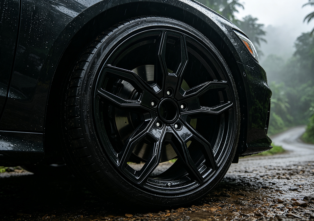
The structural capability and weight profile of any wheel design depend directly on how the underlying metal is processed. Aluminum alloys remain the industry standard, but the manufacturing method fundamentally shapes the internal grain structure and final strength-to-weight ratio.
| Feature | Cast Wheel Design | Flow-Formed Wheel Design | Forged Wheel Design |
|---|---|---|---|
| Production Method | Molten aluminum poured into static molds | Cast face spun and hydraulically stretched | Machined from solid, ultra-compressed aluminum billets |
| Grain Structure | Porous, random orientation | Compacted, directional barrel grains | Ultra-dense, continuous grain flow lines |
| Relative Strength | Standard structural rating | High radial impact strength | Maximum tensile strength & fatigue resistance |
| Unsprung Mass | Heaviest profile | Moderate weight reduction | Lightest engineering profile |
| Best Application | Daily commuting, budget OE replacement | Performance street, track use, EV upgrades | High-end motorsports, heavy off-roading, premium builds |
Cast Wheel Construction
In traditional gravity or low-pressure casting, liquid aluminum fills a pre-shaped mold. While cost-effective and versatile for complex visual styling, cast alloys possess a looser internal grain structure. To meet mandatory safety load ratings, engineers must add extra material, resulting in a heavier overall product.
Flow-Formed Technology
Flow-forming bridges the gap between casting and full forging. The wheel center is cast, but the outer barrel is spun under extreme heat and high-pressure hydraulic rollers. This process stretches and compresses the metal, aligning the aluminum grain structure parallel to the rim barrel. The result is a drastically thinner, stronger rim wall with higher tensile strength and reduced rotational mass.
Fully Forged Engineering
Forged wheel design represents the pinnacle of structural optimization. A solid block (billet) of 6061-T6 aluminum is subjected to thousands of tons of forge press pressure. This process eliminates internal porosity and aligns the alloy’s crystalline structure along the natural contours of the wheel face. CNC milling machines then carve away unneeded material, producing an ultra-lightweight frame that withstands extreme lateral forces.
3.Aerodynamic Efficiency vs. Thermal Management
As electric vehicles (EVs) become more prominent, aerodynamics has transformed how engineers approach wheel styling. Rotational drag around open wheel wells accounts for up to 25% of a vehicle’s total aerodynamic resistance.
  CLOSED / AERO-OPTIMIZED DESIGN                    OPEN-SPOKE PERFORMANCE DESIGN
          Smooth Outer Surface                            Deep Open Passages
  ┌───────────────┐           ┌─────────────────┐
  │ ┌────────────┐ │           │ ╲       │        │        ╱  │
  │ │  Turbulence Reduced    │ │           │  ╲      │        │       ╱   │
  │ │   [Range Extended]     │ │           │   ╲     │        │      ╱    │
  │ └────────────┘ │           │         [Brake Heat Vents]       │
  └───────────────┘           └─────────────────┘
Aero Wheels and Drag Reduction
Wheel designs with closed faces, flush disc inserts, or narrow perimeter blade openings keep turbulent airflow attached to the sides of the vehicle rather than spilling into the wheel wells. Minimizing air pocket creation significantly lowers the drag coefficient. On electric platforms, replacing standard open-spoke rims with aero-optimized wheels can increase highway driving range by 3% to 6%.
Brake Cooling Dynamics
The compromise lies in thermal management. Friction braking converts kinetic energy into intense heat. Open-spoke or directional fan geometries pull cool ambient air across the brake rotors and exhaust hot gases outward. Closed aero disc designs restrict this thermal transfer. As a result, engineers must carefully balance aero efficiency with thermal dissipation based on the vehicle’s intended use.
4.The Structural Mechanics of Spoke Geometry
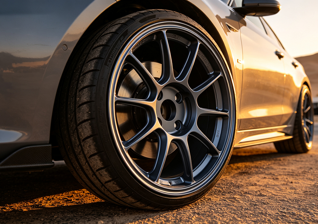
The arrangement and profile of spokes do more than define a wheel’s visual character; they form the primary load paths that distribute weight, cornering stress, and vertical impact forces.
       5-SPOKE CLASSIC                                     Y-SPOKE / MESH
       Direct Load Vectors                        Multi-Directional Load Distribution
        ┌──────┐                                   ┌──────┐
        │    ││    │                                   │   ╱  ╲   │
    ──┘    ││    └──                           ──┘  ╱    ╲  └──
    ──┐    ││    ┌──                           ──┐  ╲    ╱  ┌──
        │    ││    │                                   │   ╲  ╱   │
        └──────┘                                   └──────┘
-
Classic 5-Spoke Patterns: Straight radial spokes provide a direct mechanical connection between the center hub and the outer rim barrel. This clean layout offers high radial load support and allows maximum space for large multi-piston brake calipers.
-
Y-Spoke and Mesh Configurations: Complex mesh patterns divide incoming energy across multiple branching load paths. Because structural forces are split among more intersection points, engineers can reduce individual spoke thickness. This yields an exceptionally high strength-to-weight ratio.
-
Concave Face Profiling: Concave spokes angle inward toward the center cap. This geometry deepens the wheel’s structural profile, adding lateral rigidity to resist flex during hard, high-g cornering.
5.Understanding Fitment Geometry: Offset, Backspacing, and Hub Centricity
Even the most structurally sound wheel design will compromise vehicle performance if its mounting dimensions are incorrect. Achieving proper fitment requires precise attention to wheel geometry.
                    WHEEL OFFSET (ET) DIAGRAM
             Front Face                       Rear Face
                │                               │
                │       Centerline              │
                │           │                  │
                ▼           ▼                  ▼
             ┌──┬──────────┬───┐
             │    │        │          │      │
             │    │        │          │      │
  Positive   │    │  ┌──┼──┐    │      │   Negative
  Offset     │    │  │    │    │    │      │   Offset
  (ET > 0) ─┼──┼─┼──┼──┼──┼───┼── (ET < 0)
             │    │  └──┼──┘    │      │
             │    │        │          │      │
             └──┴──────────┴───┘
                             ▲
                             │
                        Hub Mounting
                          Surface
Wheel Offset (ET)
Offset is the distance (measured in millimeters) from the wheel’s true mechanical centerline to its hub mounting surface:
-
Positive Offset (High ET): The hub mounting surface sits closer to the front face of the wheel. Common in front-wheel drive and modern all-wheel drive vehicles.
-
Zero Offset: The mounting surface aligns exactly with the wheel’s geometric centerline.
-
Negative Offset (Low ET): The mounting surface sits deep toward the back of the wheel, pushing the outer rim edge outward for a wider stance. Popular on off-road trucks and widebody race cars.
Incorrect offset disrupts the vehicle’s scrub radius—the distance between the steering axis center point and the tire contact patch footprint. Altering this balance can induce unwanted torque steer, accelerate tire wear, and cause contact between the rubber, inner wheel liners, and suspension struts.
Hub-Centric vs. Lug-Centric Fitment
High-performance wheel designs utilize a hub-centric center bore engineered to match the vehicle’s hub snout exactly. This centering carries the structural weight of the chassis on the steel hub flange rather than putting shear load on the wheel studs.
Conversely, universal lug-centric fitments rely solely on tapered lug nuts to center the wheel. Without precise center rings, lug-centric setups are prone to high-speed rotational vibrations.
6.How Unsprung Weight Impacts Vehicle Dynamics
In chassis engineering, vehicle mass is divided into sprung weight (everything supported by the suspension springs, like the frame, engine, and passengers) and unsprung weight (components directly connected to the road surface, including wheels, tires, brake assemblies, and hub bearings).
Removing mass from the wheel assemblies yields a compound mechanical benefit. Because wheels act as heavy rotating flywheels, reducing their weight lowers both total unsprung mass and rotational inertia.

Because mass at the outer rim barrel carries a squared radius term in rotational physics, lightweight flow-formed or forged rim designs provide noticeable performance gains:
-
Enhanced Suspension Responsiveness: Lighter wheels allow shock absorbers and springs to react faster to sudden road imperfections, keeping the tire contact patch firmly planted on the pavement.
-
Sharper Acceleration and Braking: Less rotational inertia means the drivetrain spends less energy spinning the wheels up to speed, and the brake rotors require less kinetic energy to bring them to a complete stop.
-
Improved Fuel Economy and Range: Decreasing rotational resistance lowers the continuous torque required from internal combustion engines or electric vehicle motors.

Frequently Asked Questions(FAQ)
1.What factors must be considered in automotive wheel design?
Engineers must balance structural integrity (load capacity and impact resistance), performance engineering (weight reduction, brake cooling, and aerodynamics), and fitment specifications (bolt pattern, offset, and center bore) to ensure safety and driving performance.
2.How does wheel design affect vehicle aerodynamic efficiency?
Wheel geometry dictates airflow turbulence around the wheel arches. Closed or aero-optimized designs smooth external airflow to reduce drag and extend EV driving range, while open-spoke designs improve brake ventilation at the expense of higher aerodynamic resistance.
3.What is the difference between cast, flow-formed, and forged wheel designs?
-
Cast: Molten aluminum is poured into a mold; cost-effective but heavier and less dense.
-
Flow-Formed: Features a cast center with a hydraulically stretched rim barrel, yielding a lighter and stronger structure than standard casting.
-
Forged: Machined directly from a solid block of compressed aluminum, offering maximum structural strength and the lowest possible weight.
4.Why is offset crucial in wheel design and fitment?
Offset (ET) measures the distance from the wheel’s mounting hub to its centerline. An incorrect offset alters steering geometry, disrupts suspension clearance, and causes tires to rub against fenders or brake calipers.
5.How does spoke geometry impact wheel strength and weight?
Spoke geometry dictates how stress distributes under load. Multi-spoke, Y-spoke, or mesh configurations distribute impact forces across multiple load paths, allowing engineers to thin out material and reduce unsprung weight without sacrificing structural rigidity.
Optimize Your Vehicle’s Performance Profile
A vehicle’s wheels bridge the gap between engineering theory and real-world performance. Choosing the right wheel design means evaluating structural strength, manufacturing metallurgy, aerodynamic efficiency, and precise fitment geometry.
Whether you are upgrading an electric vehicle to maximize range, building a track car where every ounce of rotational weight counts, or outfitting a truck for rugged off-road durability, selecting expertly engineered wheels ensures your vehicle performs at its absolute peak.
Explore precision-engineered wheel solutions, detailed fitment specs, and advanced custom wheel options built for your driving needs at ATK Wheels.